Dell Powerconnect switches can be stacked together for for a single logical switch. In adition, the stacking module provides 10Gb throughput between the physical switches which reduces the bottleneck effects enclontered when connecting switches together via an Ethernet cable.
You will need a Dell Powerconnect 6224 or 6248 switch or any other model that has an expansion slots. Some switches, like the 3224 and 3248 models do not have expanshion slots and cannot be stacked.
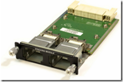
You will need to install a CX4 stacking module (PN 45W0464) on each switch. The CX4 module is shown below.
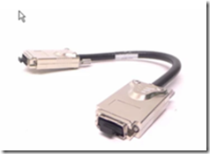
You will also need a CX4 stacking cable. The part number varies depending on the length.
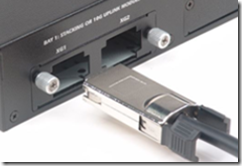
Insert the stacking module into the expansion port of each switch and connect the stacking cable as showb below.
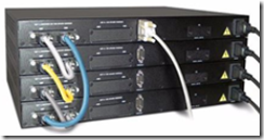
You can stack up to 12 switches together. Connect the cables in a cross cable layout (also known as a ring). A group of stacked switches will look something like this:
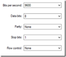
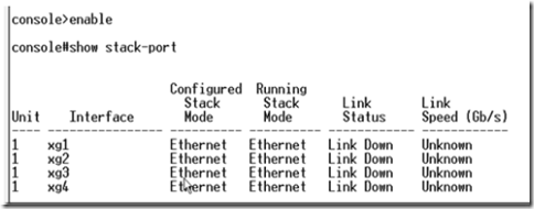
By default, the XG1-XG4 interfaces are set to Ethernet (see below). They need to be set to stacking mode. Connect to the switch console using a serial interface and terminal emulation program (9600 baud, 8 data bits, no parity, 1 stop bit, no flow control)
Execute command show stack-port while in enable mode.
In the console, type the configure command to enter into config mode, then the stack command to enter into stack configuration mode. Next, enter the command stack-port 1/xg1 stack to set the interface into stack mode. Simply replace the unit number and interface to set the desired interface. In the example, below, XG4 interface is being set to stack mode.
Enter the exit command twice to go back out of configuration mode and use the show stack-port command to view the stack configuration. The interface you changed should now show as stack configuration.
Execute the copy run start command to save the running configuration so that you don’t lose your changes!
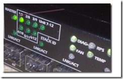
Repeat the above configuration process for all the switches in the stack. When finished, restart all the switches to load the new running configuration. One of the switches will have the MASTER LED on. Connect to this switch using the console as this will be the main management switch.
Switches with different OS versions will not properly stack. Use the show stack-ports command to view the switch code versions. Switches with mismatched code versions will need to be updated.
You can download the latest firmware versions for the Powerconnect 6224 and 6248 here and there are several ways to proceed with firmware updates on a stack. You can opt for an automatic update using firmware synchronization or simply manually upload the same firmware to all the stack members. You can get details on this procedure as well as other information about stacking when you read the fine manual for the 6200 series switches. If you don’t want to read the manual, here’s a synopsis below.
By far the easiest route is to upload the newest image code using the Web UI and have it transferred to the other units. To do this, you will need a TFTP server with a copy of the image code and it must be accessible to the switch. Assign the switch an IP address using the IP address command (from the config menu).
Example: IP Address 10.10.10.1 255.255.255.0
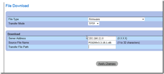
Access the switch using the Web UI and navigate to the file management –> file download section. Enter the IP address of the TFTP server and the image name.
The image will be distributed to all the units in the stack. From the file management –> active images menu, select the secondary image on all devices so that they load the same image after reboot.
Restart all the devices and they should now all have the same code version.

