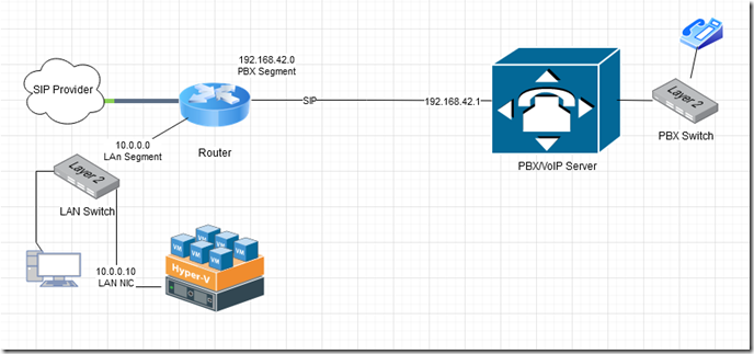
In this post, we will create a design based on an Avaya IP500 PBX and Xima voice recording software however, these instructions can be used for a variety of similar systems since the underlying technology is the same. In our example, we have a router which passes SIP traffic to the Avaya PBX for VoIP telephony. The Xima software captures the SIP traffic in order to record conversations and create call logs. The Xima software runs as a virtual guest in Hyper-V.
The first step in our design is to tap into the existing SIP traffic without disrupting it. To do this, we insert a mirror-capable layer2 switch in between the router and the PBX. I personally use high-quality switches (Dell EMC X series or Cisco Catalyst) for reliability and stability however to keep this lab project simple and frugal, we are going to use a low-cost Netgear intelligent switch which you can purchase at your local office supply store. For the price, these units work fairly well even under high workloads.
Our starting scenario is depicted below. A typical setup where the network is segmented between data and voice.
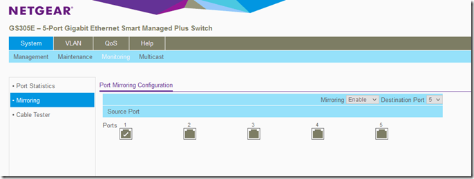
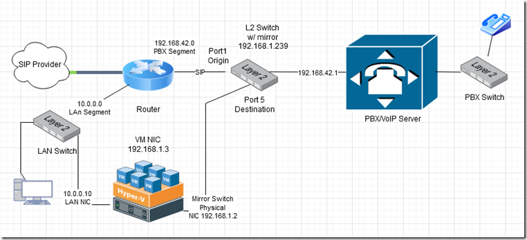
We will insert our port mirror switch into the voice network segment between the router’s LAN interface and the PBX’s WAN/LAN interface. Our port mirroring configuration sets port 1 as the origin and port 5 as the destination. This means that all traffic that traverses port 1 (into any other port) will be mirrored on port 5. You can see the configuration depicted below.
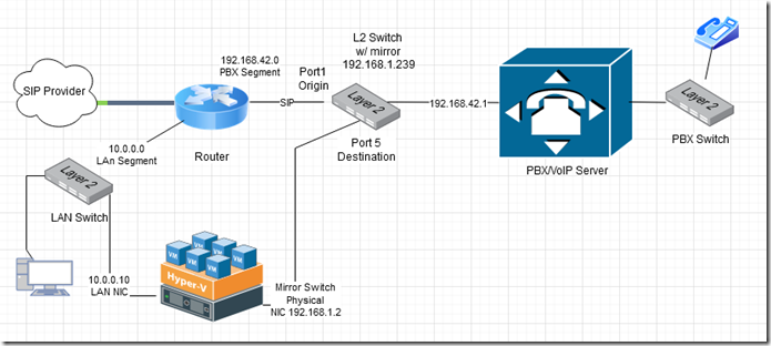
Although port mirroring is a layer 2 function, I am going to configure the GS305E with the IP address 192.168.1.239 so that we can access its management interface from the VM in case we need to in the future. You can give it any IP address outside your current IP segments. This network segment 192.168.1.0/24 will be assigned as our mirror/packet capture LAN segment so the mirror switch’s management IF and the packet capture NICs will all have IP addresses within this range.
In the updated diagram shown above, we have inserted the switch and connected the origin IF port 1 to the router and the destination IF port 5 to the Hyper-V server’s secondary physical NIC. The PBX can then be connected to any of the non-mirrored ports (2-4).
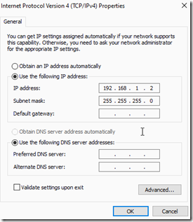
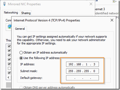
Next, rename the LAN adapter on the Hyper-V server something that will help you identify it and assign the IP address 192.168.1.2 and subnet mast 255.255.255.0 to it. Note: DO NOT add a default gateway; Windows servers do not support multi-gateway protocols! If you want to avoid capturing broadcast traffic, unbind any unwanted protocols.
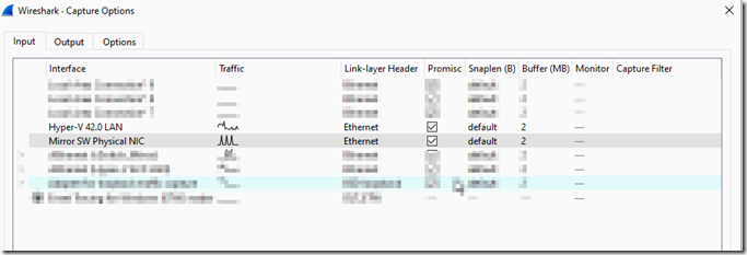
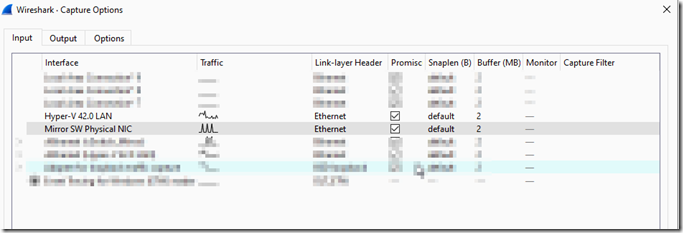
Download and install Wireshark on the Hyper-V host. Wireshark will set the NICs into promiscuous mode by default. Go to the capture –> options menu and unselect promiscuous mode from the NICs that will not be part of the packet capture network.
If you do not plan on installing Wireshark, follow these instructions to put the NICs into promiscuous mode:
1. Open powershell as administrator and run this command to get the MAC address of the network adapter .
Get-VM -Name virtual machine name | Get-VMNetworkAdapter
2. Then run the following command to turn on promiscuous mode for all packet capture network adapters .
Get-VM -Name virtual machine name | Get-VMNetworkAdapter | Where-Object { $_.MacAddress -eq “MAC address” } | Set- VMNetworkAdapter -MacAddressSpoofing On
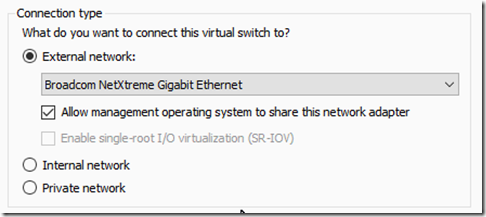
Open the Hyper-V switch manager and add an external switch and assign it to the packet capture NIC.
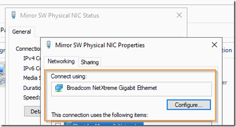
The drop down menu will show all the Hyper-V server’s physical NICs using their descriptive name. If you are not sure which is the packet capture NIC, open the NIC’s properties OR use the Get-NetAdapter PowerShell command to make the correlation.
Next we need to add the secondary NIC from the packet capture LAN to the virtual machine. To do this, shut down the VM then go to its settings.
Select add hardware and add a new network adapter. In the advanced features, set the port mirror mode as destination as shown below.
Start the VM again and in the VM’s NIC, assign it an IP address from the packet capture segment subnet. Make sure to leave the default gateway blank and unbind any broadcast protocols if you don’t want the unnecessary traffic.
Once you apply the settings, you should be able to ping the packet capture router (192.168.1.239) as well as the Hyper-V host physical server’s capture packet NIC (192.168.1.2).
Download and install Wireshark on the VM to test packet capture.
We will be using Wireshark for packet capture. Wireshark will set the NICs into promiscuous mode by default. Go to the capture –> options menu and unselect promiscuous mode from the NICs that will not be part of the port mirroring.
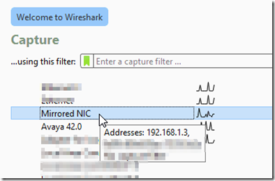
Select the packet filter NIC by double clicking it to open.
From the Wireshark menu, select telephony –> SIP flows and you should be able to see the SIP traffic being captured.
The completed design is depicted below.

