SonicWall offers a high availability feature that allows your SonicWall firewall to automatically fail over to a backup if the primary firewall fails.
- To use this feature, you must have two identical model firewalls.
- High availability will not work on SonicWall wireless models. If you are using a wireless model firewall, you must disable the wireless feature.
- Older model firewalls such as the Pro 3060 must have enhanced firmware in order for you to access the high availability feature.
- After completion, perform a failover tests to make sure that your configuration works. Don’t wait for a real failover to learn something is not right!
To begin, select a primary and backup firewall. It’s a good idea to label them in order to avoid confusion. At this stage, it’s the perfect time to update the firmware version on the primary firewall. When you connect both devices, the updated firmware and settings will be copied to the backup firewall. It’s a good idea to have the latest firmware loaded.
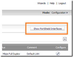
Disable all the PortShield interfaces on both firewalls. To do this, navigate to network –> interfaces and click on the show PortShield interfaces button.
Click on the configure icon next to the PortShield interfaces to edit them.
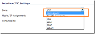
Change the zone to unassigned. Repeat this process until all PortShield interfaces on both firewalls are unassigned.
Log in to the primary firewall and configure the firewall’s LAN & WAN settings along with any other customizations you may want to use, e.g. port forwarding, DHCP, etc.
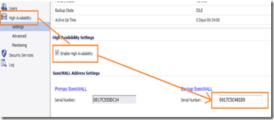
Navigate to high availability and enable it by ticking on the high availability check box and clicking on the apply button. In the backup SonicWall text box, enter the backup firewall’s serial number as shown on the bottom (or back) of the backup unit, then click apply.
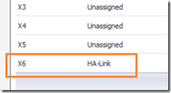
Navigate to network –> interfaces and look for the high availability HA- Link. Depending on your SonicWall model, the interface number may be different because some models have more interface ports than others. Regardless of model, it will always be the last interface that is assigned as the high availability link. In the example shown below, it’s interface X6.
Connect an Ethernet crossover cable from the HA-Link Interface of the primary firewall to the same interface on the backup firewall. Note: it must be a crossover cable, straight through cables will not work!
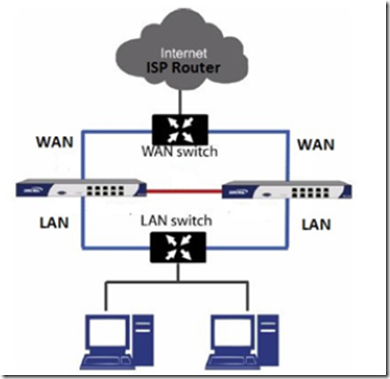
Connect both firewall’s LAN ports to the LAN switch and both firewall’s WAN ports to a switch that is connected to your ISP’s router/modem. Your connections should look like the connection is the diagram below.
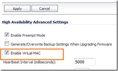
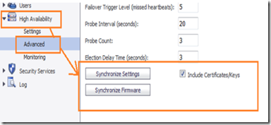
Navigate to high availability –> advanced and make sure that the include certificate keys and enable virtual MAC options are checked. Switches and ISP modems may need a restart to clear their ARP cache after a failover if the virtual MAC option is not enabled. For this reason, it’s a good idea to enable the virtual MAC address.
It’s also important that certificate keys are synchronized across both devices which is what the include certificate keys option does.
Next, click on the synchronize firmware button. This will ensure that both devices have the same firmware version. When the firmware has been synchronized, do the same to synchronize the settings.
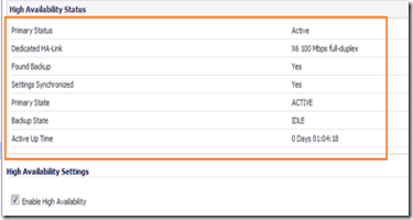
When this process is complete , navigate to high availability –> settings and your status settings should look like the one in the image below.
You can test the high availability functionality by taking the primary unit off line and waiting for the backup unit to fail over.
There are advanced settings you can modify to meet your needs, read below for details. Note: These options may not be available on all models.
- Preempt Mode. This feature controls the behavior in which the Primary unit will seize the Active role from the Backup after it recovers from an error condition, reboot or firmware upgrade, after it successfully communicates to the backup unit that it is in a verified operational state.
- Enable Virtual MAC. Virtual MAC allows the Primary and Backup appliances to share a single MAC address. This greatly simplifies the process of updating network routing tables when a failover occurs. Only the WAN or LAN switch to which the two appliances are connected needs to be notified. All outside devices will continue to route to the single shared MAC address.
- Heartbeat Interval to control how often the two units communicate. The default is 5000 milliseconds; the minimum recommended value is 1000 milliseconds. Less than this may cause unnecessary failovers, especially when the SonicWALL is under a heavy load.
- Probe Level for the interval in seconds between communication with upstream or downstream probe targets. SonicWALL recommends that you set the interval for at least 5 seconds.
- Heartbeat Interval (seconds) – This timer is the length of time between status checks. By default this timer is set to 5 seconds; using a longer interval will result in the SonicWALL taking more time to detect when/if failures have occurred.
- Failover Trigger Level (missed heart beats) – This timer is the number of heartbeats the SonicWALL will miss before failing over. By default, this time is set to 5 missed heart beats.This timer is linked to the Heartbeat Interval timer – for example, if you set the Heartbeat Interval to 10 seconds, and the Failover Trigger Level timer to 5, it will be 50 seconds before the SonicWALL fails over.
- Election Delay Time – This timer can be used to specify an amount of time the SonicWALL will wait to consider an interface up and stable, and is useful when dealing with switch ports that have a spanning-tree delay set.
- The Dynamic Route Hold-Down Time – This setting is used when a failover occurs on a High Availability pair that is using either RIP or OSPF dynamic routing. When a failover occurs, Dynamic Route Hold-Down Time is the number of seconds the newly-Active appliance keeps the dynamic routes it had previously learned in its route table. During this time, the newly-Active appliance relearns the dynamic routes in the network. When the Dynamic Route Hold-Down Time duration expires, it deletes the old routes and implements the new routes it has learned from RIP or OSPF. The default value is 45 seconds. In large or complex networks, a larger value may improve network stability during a failover.

